DC Motor Control Using Arduino

Planning out Circuit Schematic

I used Tinker CAD For fast prototyping and code testing.

Need to know terms:

  • Electronic circuit?
    An electronic circuit is composed of individual electronic components, such as resistors, transistors, capacitors, inductors and diodes, connected by conductive wires or traces through which electric current can flow.
  • L293D?
    controls the flow of power and how is it connected including direction and speed to the high voltage motors in this project
  • Arduino uno?
    An Arduino Uno is a microcontroller board designed for beginners and hobbyists: It is an open-source platform, making it easy to use and modify for various projects. An Arduino Uno has input and output pins that allow you to connect sensors, actuators, and other components. With its user-friendly integrated development environment (IDE), you can write and upload code to control electronic devices, making it an excellent choice for prototyping and learning electronics.
  • TinkerCAD?
    an easy-to-use online tool for creating 3D models and electronic circuits. You can drag and drop shapes to design objects and simulate circuits without needing advanced skills or software. It's great for beginners and educational purposes.
  • 5v (volt) regulator?
    A 5-volt regulator is an electronic component that takes in a higher voltage input and provides a stable 5-volt output. It ensures that the voltage remains constant at 5 volts, regardless of any fluctuations or variations in the input voltage, making it useful for powering various electronic devices that require a steady 5-volt power supply.
  • DC motor? is an electrical device that turns electricity into movement. It has a spinning part (armature) and uses magnets to rotate when you apply power to it. DC motors are used in things like fans, toys, and many other devices that need motion.
  • ATTINY? is a type of small and low-power computer chip used in many electronic projects. It's good for small gadgets and devices like robots and wearable tech. uses very low power and is very small, very cool!
Mobirise Website Builder

this is an advanced electrical version of the same basic circuit

Mobirise Website Builder

this is a basic circuit I used for testing and to get to know the L293D
(controls the flow of power and how is it connected)
module we are using an ATTINY as the microcontroller
(device that controls the L293D and also the device we program) in this.

Mobirise Website Builder

this is an advanced electrical version of the same Arduino circuit

Mobirise Website Builder

updated schematic for Arduino Uno instead of ATTINY we had to change the code and the format of the code due to Arduino Uno using a different format

Mobirise Website Builder

a test of possible chemical battery configurations in this circuit 

Mobirise Website Builder

he we see the number of rotations a minute 16530 (rpm) a hypothetical dc motor would achieve provided the 9v volts from the chemical battery

Mobirise Website Builder

a test of possible chemical battery configurations that could be chained together to achieve a higher voltage in this circuit in this config we use 3 of the 9 volt batteries to create a 23.8v flow of power

Mobirise Website Builder

 23.8v volts from the chemical battery = ~47469 rpm

Mobirise Website Builder

because we are using the Arduino Uno we use the Arduino IDE

Code Breakdown!

Step 1: Setup and definition 

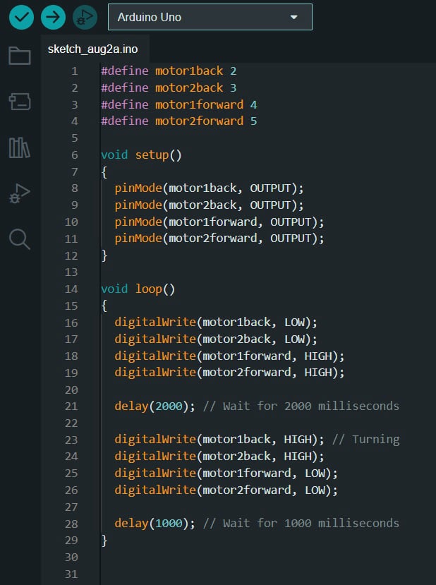
The #define preprocessor directives create symbolic names for the four motor control pins: motor1back (pin 2), motor2back (pin 3), motor1forward (pin 4), and motor2forward (pin 5).

In the setup() function, the four motor control pins are set as OUTPUT, indicating that these pins will be used to control the motors.

In the loop() function, the motors are controlled in the following pattern:

Step 2: Moving the motors forward

Pins 4 and 5 (motor1forward and motor2forward) are set HIGH to move the motors forward.
Pins 2 and 3 (motor1back and motor2back) are set LOW to ensure they are not active in this direction.
A delay of 2000 milliseconds (2 seconds) occurs using delay(2000);.

Step 3: Stopping the motors (moving backward)

Pins 4 and 5 (motor1forward and motor2forward) are set LOW to stop the motors from moving forward.
Pins 2 and 3 (motor1back and motor2back) are set HIGH to move the motors backward.
A delay of 1000 milliseconds (1 second) occurs using delay(1000);.

The loop then repeats, going back to Step 1 and moving the motors forward again, creating a continuous forward-backward motion pattern for the motors.

Mobirise Website Builder

zoomed in shot of dc motor

Ripping Apart robot shell

Using an old shell of a robot cat toy that used 2 dc motors and 1 rotating plastic wheel for movement. added a small breadboard, then soldered connections to the 2 dc motors of the toy.
(note: none of the electronics other then the 2 dc motors of the toy were used)
after that I configured the dc motors as show in the schematic above using the code as described in the previous section

Mobirise Website Builder

GIF example of program moving forward for 2 seconds and back for 1

DC Motor Demo

here we see one of the motors with the current code we broke down above

video demos of 2 assembled circuts

w

ATTINY Test

Uno Test

I hope you enjoyed my first article!

more interesting and exciting projects coming very soon!

Drag & Drop Website Builder